
WENZHOU PROM TRADING CO.,LTD.
Contact Person:Lucy Guo
Tel/Wechat/Watsapp:+86 15990723109
E-mail: promtrading@sina.com
Skype:lucysolac
Legal Add:Room 804, Block 15, Jinlongyuan, No.81, Nixiang South Road, Kunpeng Street, Wenzhou Maritime Economy Development Demonstration Zone, Wenzhou, Zhejiang, China
Factory Add:Binhai industrial zone, Longwan, Wenzhou, Zhejiang, China
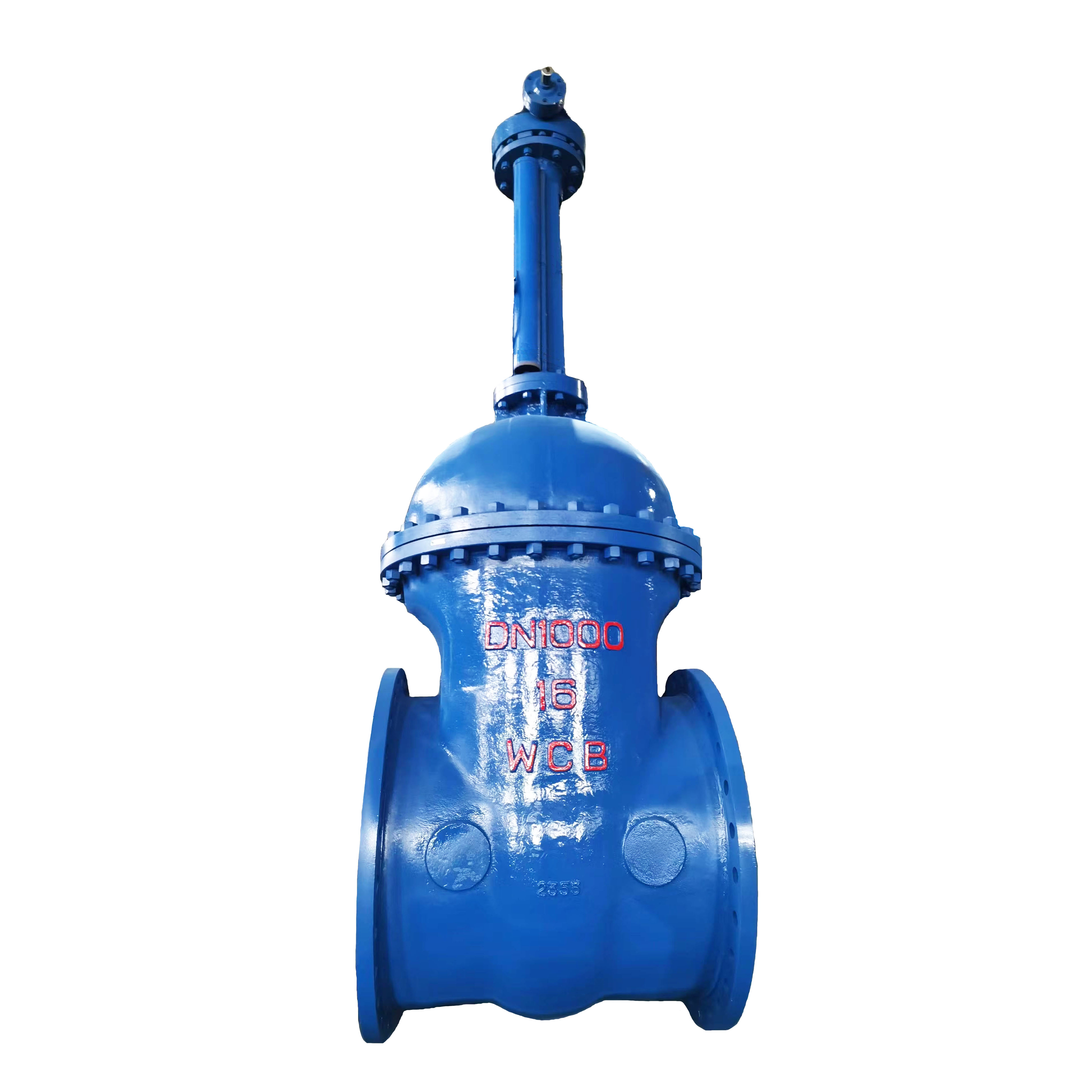
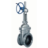
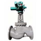
RISING STEM FLANGED GATE VALVE WIGH GEAR
Flanged wedge gate valve with rising stem with gearbox
The steel wedge gate valve with a retractable flanged spindle is designed for installation on pipelines with diameters of DN - 50, 65, 80, 100, 125, 150, 200, 250, 300, 350, 400, 450, 500, 600, 700, 800, 900, 1000 as a shut-off device, at pressures up to 16.0 MPa and temperatures up to +425C. On a vertical pipeline in the (flat) position with a horizontal spindle arrangement.
Technical specifications: Working medium - liquid and gaseous non-aggressive petroleum products, water, steam at temperatures up to +425C
Seal tightness - class "A" (without leakage)
Nominal pressure PN, MPa (kgf/cm2) - 1.6-16.0 (16-40)
The connection to the pipeline is flanged
Body material – WCB steel
The material of the gate seal is stainless steel
The drive is manual (gearbox)
Device and operating principle
In general, the valve design consists of a body and a lid forming a cavity in which the working medium is under pressure and inside which the valve is placed. The body has two ends for connecting the gate valve to the pipeline (flanged, coupling and welded connection ends are used). There are usually two seats inside the housing, parallel or at an angle to each other, and the sealing surfaces of the gate are pressed against their sealing surfaces in the "closed" position. The shutter moves in a plane perpendicular to the axis of passage of the medium through the housing, using a spindle or rod. The spindle with the running nut forms a threaded pair, which, when one of these elements rotates, ensures that the shutter moves in the desired direction. This solution is most common and is used for manual or electric control. When using a hydraulic or pneumatic actuator, the rod performs only translational motion together with the gate. The spindle is connected to the gate with one end inside the housing, and the other end passes through the cover and the stuffing box (which is mainly used as a sealing device in gate valves) to connect to the gate valve control.
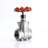
Designs of locking bodies of wedge gate valves In wedge gate valves, the seats in the housing are positioned at a slight angle to each other, and the gate is a device in the form of a wedge — rigid, elastic or two-disc, which in the "closed" position fits tightly into the space between the seats. Depending on the operating conditions, one or another type of wedge is selected.
A hard wedge
The rigid wedge ensures reliable tightness of the locking body, but this requires increased machining accuracy to match the angle of the wedge with the angle between the housing seats. The disadvantage of a rigid wedge is the danger of jamming the valve and the inability or difficulty of opening the valve as a result of fluctuations in the temperature of the working medium, wear or corrosion of the sealing surfaces.
Two-disc wedge
Such a wedge is formed by two discs positioned at an angle to each other and rigidly fastened together. In it, the discs have the ability to self-install relative to the housing seats, so some errors allowed in the manufacture of housing seats do not affect the tightness in the "closed" position. The two-disc wedge gate significantly reduces the possibility of jamming, which is characteristic of a rigid wedge, and, despite some design complexity, has a number of other advantages — low wear on the sealing surfaces, high tightness of the locking body, and less force required for closing. Wedge double-disc valves included in marine fittings are also called wedge valves.
Elastic wedge
This is a modification of a two-disc wedge, the discs of which are interconnected by an elastic element capable of bending, providing tight contact between the sealing surfaces in the "closed" position. In this valve, the possibilities of self-mounting discs are reduced compared to two-disc ones, although the ability to compensate for some deformations of the housing from pipeline loads and temperature fluctuations remains. The advantages of an elastic wedge are that it does not require a laborious fitting of the bolt to the body (as for a rigid wedge) and the design is simpler than that of a two—disc one. Thus, the elastic wedge smooths out the disadvantages to a certain extent and combines the advantages of the other two types of wedge valves.
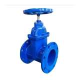
Sliding spindle gate valve
In this design, the spindle thread and the lead nut are located outside the valve body. The lower end of the spindle is connected to the shutter and, when the travel nut rotates to open the gate valve, it performs only translational movement with the shutter, while the upper end of the spindle extends by the stroke of the shutter. To allow the spindle to move, the travel nut is raised above the top of the lid (that is, above the oil seal) by about the stroke of the bolt in a design called a yoke assembly. The advantages of this design are the absence of harmful effects of the working environment on the running assembly and free access for its maintenance, and therefore less wear of the stuffing box and higher reliability of the threaded pair and stuffing box. The disadvantage of such valves is an increase in the construction height and weight due to the exit of the spindle from the lid by at least the diameter of the passage and the need for this reason to leave free space for the exit of the spindle during installation.
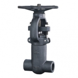
Materials and manufacturing methods
The sealing surfaces of the valves are made without rings, with rings made of brass, fluoroplast, surfaced with corrosion-resistant steel, and rubber (in wedge valves, a wedge can be covered with it, and in hose valves, a clamping hose is made from it). Valves with cast iron and aluminum alloy housings are made by casting. Steel gate valves are made in the same way, but some of them, as well as valves made of titanium alloys, are made by welding blanks obtained by stamping from rolled steel. Such valves are called stamp-welded. In terms of their performance and strength characteristics, they are not inferior to cast valves, but on the contrary, the parts of the housings and covers of such valves are made of a more durable and carefully controlled material, the quality of which is higher than casting. At the same time, welding technology and methods of inspection of welded joints ensure high-quality body parts, allowing such valves to be used at critical facilities, including nuclear power.
Drawing of a cast steel gate valve with rising stem

Materials of Main Parts
| № | Part Name | Material |
| 1 | Body | WCB |
| 2 | Disc | WCB+2Cr13 |
| 3 | Stem | 2Cr13 |
| 4 | Stud | Сталь35 |
| 5 | Nut | Сталь45 |
| 6 | Gasket | 304+graphite |
| 7 | Bonnet | WCB |
| 8 | Packing | Flexible graphite |
| 9 | Штифт | 2Cr13 |
| 10 | Gland | WCB |
| 11 | Yoke | WCB |
| 12 | Gear | Grey Iron |
Main Size & Weight
| PN, MPa | DN, mm | L | D | D1 | D2 | n-фd | H≈ |
| 1,6 | 50 | 180 | 160 | 125 | 102 | 4-ф18 | 678 |
| 65 | 200 | 180 | 145 | 122 | 4-ф18 | 693 | |
| 80 | 210 | 195 | 160 | 133 | 4-ф18 | 755 | |
| 100 | 230 | 215 | 180 | 158 | 8-ф18 | 820 | |
| 125 | 255 | 245 | 210 | 184 | 8-ф18 | 934 | |
| 150 | 280 | 280 | 240 | 212 | 8-ф22 | 994 | |
| 200 | 330 | 335 | 295 | 268 | 12-ф22 | 1138 | |
| 250 | 450 | 405 | 355 | 320 | 12-ф26 | 1409 | |
| 300 | 500 | 460 | 410 | 370 | 12-ф26 | 1588 | |
| 350 | 550 | 520 | 470 | 430 | 16-ф26 | 1755 | |
| 400 | 600 | 580 | 525 | 482 | 16-ф30 | 1902 | |
| 450 | 650 | 640 | 585 | 532 | 20-ф30 | 2141 | |
| 500 | 700 | 710 | 650 | 585 | 20-ф33 | 2276 | |
| 600 | 800 | 840 | 770 | 685 | 20-ф39 | 2474 | |
| 700 | 900 | 910 | 840 | 800 | 24-ф39 | 3046 | |
| 800 | 1000 | 1020 | 950 | 905 | 24-ф39 | 3250 | |
| 900 | 1100 | 1120 | 1050 | 1005 | 28-ф39 | 3509 | |
| 1000 | 1200 | 1255 | 1170 | 1110 | 28-ф45 | 3873 |
| PN, MPa | DN, mm | L | D | D1 | D2 | n-фd | H≈ |
| 2,5 | 50 | 250 | 160 | 125 | 100 | 4-ф18 | 678 |
| 65 | 265 | 180 | 145 | 120 | 8-ф18 | 693 | |
| 80 | 280 | 195 | 160 | 135 | 8-ф18 | 755 | |
| 100 | 300 | 230 | 190 | 160 | 8-ф23 | 820 | |
| 125 | 325 | 270 | 220 | 188 | 8-ф25 | 934 | |
| 150 | 350 | 300 | 250 | 218 | 8-ф25 | 994 | |
| 200 | 400 | 360 | 310 | 278 | 12-ф25 | 1138 | |
| 250 | 450 | 425 | 370 | 332 | 12-ф30 | 1409 | |
| 300 | 500 | 485 | 430 | 390 | 12-ф30 | 1588 | |
| 350 | 550 | 550 | 490 | 448 | 16-ф34 | 1755 | |
| 400 | 600 | 610 | 550 | 505 | 16-ф34 | 1902 | |
| 450 | 650 | 660 | 600 | 555 | 20-ф34 | 2141 | |
| 500 | 700 | 730 | 660 | 610 | 20-ф41 | 2276 | |
| 600 | 800 | 840 | 770 | 718 | 20-ф41 | 2474 | |
| 700 | 900 | 955 | 875 | 815 | 24-ф48 | 3046 | |
| 800 | 1000 | 1070 | 990 | 930 | 24-ф48 | 3250 | |
| 900 | 1100 | 1180 | 1090 | 1025 | 28-ф54 | 3509 | |
| 1000 | 1200 | 1305 | 1210 | 1140 | 28-ф58 | 3873 |
| PN, MPa | DN, mm | L | D | D1 | D4 | n-фd | H≈ |
| 4,0 | 50 | 250 | 160 | 125 | 87 | 4-ф18 | 691 |
| 65 | 280 | 180 | 145 | 109 | 8-ф18 | 711 | |
| 80 | 310 | 195 | 160 | 120 | 8-ф18 | 775 | |
| 100 | 350 | 230 | 190 | 149 | 8-ф23 | 871 | |
| 125 | 400 | 270 | 220 | 175 | 8-ф25 | 948 | |
| 150 | 450 | 300 | 250 | 203 | 8-ф25 | 1028 | |
| 200 | 550 | 375 | 320 | 259 | 12-ф30 | 1325 | |
| 250 | 650 | 445 | 385 | 312 | 12-ф34 | 1400 | |
| 300 | 750 | 510 | 450 | 363 | 16-ф34 | 1653 | |
| 350 | 850 | 570 | 510 | 421 | 16-ф34 | 1791 | |
| 400 | 950 | 655 | 585 | 473 | 16-ф41 | 2092 | |
| 450 | 1050 | 680 | 610 | 523 | 20-ф41 | 2465 | |
| 500 | 1150 | 755 | 670 | 575 | 20-ф48 | - | |
| 600 | 1350 | 890 | 795 | 677 | 20-ф54 | - | |
| 700 | 1450 | 995 | 900 | 777 | 24-ф54 | - | |
| 800 | 1650 | 1135 | 1030 | 877 | 24-ф58 | - |
| PN, MPa | DN, mm | L | D | D1 | D9 | D8 | n-фd | H≈ |
| 6,4 | 50 | 250 | 175 | 135 | 102 | 85 | 4-ф23 | 790 |
| 65 | 280 | 200 | 160 | 132 | 110 | 8-ф23 | 840 | |
| 80 | 310 | 210 | 170 | 133 | 115 | 8-ф23 | 890 | |
| 100 | 350 | 250 | 200 | 170 | 145 | 8-ф25 | 1020 | |
| 125 | 400 | 295 | 240 | 205 | 175 | 8-ф30 | 1100 | |
| 150 | 450 | 340 | 280 | 240 | 205 | 8-ф34 | 1290 | |
| 200 | 550 | 405 | 345 | 285 | 265 | 12-ф34 | 1475 | |
| 250 | 650 | 470 | 400 | 345 | 320 | 12-ф41 | 1500 | |
| 300 | 750 | 530 | 460 | 410 | 375 | 16-ф41 | 1820 | |
| 350 | 850 | 595 | 525 | 465 | 420 | 16-ф41 | 2216 | |
| 400 | 950 | 670 | 585 | 535 | 480 | 16-ф48 | 2838 | |
| 500 | 1150 | 800 | 705 | 615 | 580 | 20-ф54 | 3320 | |
| 600 | 1350 | 930 | 820 | 735 | 680 | 20-ф58 | 3684 |
| PN, MPa | DN, mm | L | D | D1 | D9 | D8 | n-фd | H≈ |
| 10,0 | 50 | 250 | 195 | 145 | 102 | 85 | 4-ф25 | 810 |
| 65 | 280 | 220 | 170 | 140 | 110 | 8-ф25 | 860 | |
| 80 | 310 | 230 | 180 | 150 | 115 | 8-ф25 | 892 | |
| 100 | 350 | 265 | 210 | 175 | 145 | 8-ф30 | 1013 | |
| 125 | 400 | 310 | 250 | 210 | 175 | 8-ф34 | 1184 | |
| 150 | 450 | 350 | 290 | 250 | 205 | 12-ф34 | 1250 | |
| 200 | 550 | 430 | 360 | 285 | 265 | 12-ф41 | 1250 | |
| 250 | 650 | 500 | 430 | 345 | 320 | 12-ф41 | 1650 | |
| 300 | 750 | 585 | 500 | 410 | 375 | 16-ф48 | 1800 | |
| 350 | 850 | 655 | 560 | 465 | 420 | 16-ф54 | 2030 | |
| 400 | 950 | 715 | 620 | 535 | 480 | 16-ф54 | 2250 |
| PN, MPa | DN, mm | L | D | D1 | D9 | D8 | n-фd | H≈ |
| 16,0 | 50 | 300 | 215 | 165 | 115 | 95 | 8-ф25 | 832 |
| 65 | 340 | 245 | 190 | 140 | 110 | 8-ф30 | 880 | |
| 80 | 390 | 260 | 205 | 150 | 130 | 8-ф30 | 905 | |
| 100 | 450 | 300 | 240 | 175 | 145 | 8-ф34 | 1071 | |
| 125 | 525 | 355 | 285 | 210 | 190 | 8-ф41 | 1163 | |
| 150 | 600 | 390 | 318 | 250 | 205 | 12-ф41 | 1170 | |
| 200 | 750 | 480 | 400 | 280 | 275 | 12-ф48 | 1440 |
*The above dimensions are for reference only.